Welcome to the Honeywell Pro 6000 Installation Manual, your comprehensive guide for installing and configuring the FocusPro 6000 Series Programmable Thermostat. Designed for professionals and DIY enthusiasts, this manual provides step-by-step instructions for wallplate installation, wiring, and system setup. It covers essential features like Auto Changeover, Adaptive Intelligent Recovery, and compressor protection, ensuring safe and efficient operation. Follow the detailed instructions to avoid electrical hazards and ensure proper system functionality. This manual also includes troubleshooting tips and specifications to help you get the most out of your thermostat.
1.1 Overview of the Honeywell Pro 6000 Thermostat
The Honeywell Pro 6000 thermostat is a programmable, Wi-Fi-enabled device designed for efficient temperature control. It supports various HVAC systems, including heat-only, heat pumps, and dual-fuel configurations. With a user-friendly interface, it offers features like adaptive intelligent recovery and compressor protection. Compatible with both battery and hardwired power, it ensures reliable operation. The thermostat is part of the FocusPro series, known for its flexibility and advanced functionality, making it suitable for residential and light commercial applications. Its compact design and intuitive programming options provide precise temperature management, enhancing comfort and energy efficiency.
1.2 Importance of Proper Installation
Proper installation of the Honeywell Pro 6000 thermostat is crucial for ensuring safe and efficient operation. Incorrect wiring or mounting can lead to electrical hazards, system malfunctions, or even equipment damage. Adhering to the installation manual prevents these risks and ensures optimal performance. Proper setup also guarantees compatibility with your HVAC system, whether it’s a heat-only configuration, a heat pump, or a dual-fuel system. Additionally, correct installation maintains the thermostat’s advanced features, such as adaptive recovery and compressor protection, which enhance energy efficiency and system longevity. Always disconnect power before starting and follow safety guidelines to avoid potential harm or voiding the warranty.

Wallplate Installation
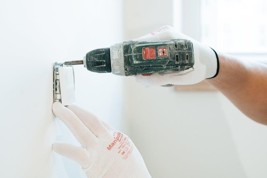
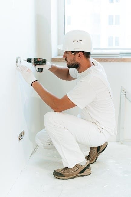
Begin by separating the wallplate from the thermostat. Mount the wallplate using anchors and screws, ensuring proper alignment. Drill holes for drywall or plaster as needed. Always disconnect power before starting to avoid electrical hazards and ensure a safe installation process.
2.1 Separating the Wallplate from the Thermostat
To separate the wallplate from the thermostat, first ensure the system is powered off for safety. Gently pull the thermostat away from the wallplate. For new installations, remove the battery holder and slide the wallplate off by gripping the unit firmly and pulling straight away. This step is crucial for accessing the wiring terminals and preparing for proper mounting. Always disconnect power before starting to avoid electrical hazards. Once separated, the wallplate can be mounted independently, ensuring a secure and level installation surface. This step ensures the thermostat is installed safely and efficiently.
2.2 Mounting the Wallplate
Mounting the wallplate securely is essential for proper thermostat installation. Begin by ensuring the area is level and clear of debris. Use a drill to create pilot holes for the mounting screws, following the manufacturer’s guidelines for drywall or plaster. Insert wall anchors into the holes to provide a sturdy base. Align the wallplate with the holes, ensuring it is flush against the wall. Screw the wallplate into place using the provided mounting screws. Tighten firmly but avoid overtightening, which could damage the wall or wallplate. Ensure the wallplate is level and secure before proceeding to the next steps. Always disconnect power before starting to avoid electrical hazards.
2.3 Drilling Holes for Drywall or Plaster
Drill pilot holes for the wallplate mounting screws, ensuring proper alignment. For drywall, use a 3/16-inch drill bit, and for plaster, use a 7/32-inch bit. Insert wall anchors into the drilled holes to provide a secure mounting surface. Align the wallplate with the holes and gently press it into place. Ensure the wallplate is level and flush against the wall. Tighten the mounting screws firmly but avoid overtightening, which could damage the wall or wallplate. Always disconnect power before starting to avoid electrical hazards. Properly drilled holes and securely installed anchors are critical for a stable installation.
2.4 Using Wall Anchors and Mounting Screws
Insert wall anchors into the pre-drilled holes to provide a stable base for mounting. Align the wallplate with the anchors, ensuring proper fitment. Use the provided mounting screws to secure the wallplate to the wall. Tighten the screws firmly to avoid any movement but avoid overtightening, which could damage the wall or wallplate. Ensure the wallplate is level and securely fastened before proceeding. This step is crucial for ensuring the thermostat operates correctly and maintains a professional appearance. Always follow safety precautions and disconnect power before starting work to prevent electrical hazards or equipment damage.
Wiring Terminal Designations
The Honeywell Pro 6000 thermostat uses labeled terminals (R, W, Y, G, C, etc.) for connections. Ensure wires are securely attached to the correct terminals to avoid electrical hazards and ensure proper system operation. Always use 18- to 22-gauge thermostat wire for compatibility. Refer to the wiring diagram in this manual for specific configurations based on your heating/cooling system type. Proper terminal connections are critical for safe and efficient thermostat functionality.
3.1 Understanding Terminal Labels
Understanding the terminal labels on your Honeywell Pro 6000 thermostat is essential for correct wiring. Each terminal (R, W, Y, G, C, etc.) has a specific function. The R terminal connects to the heating system’s power supply, while W controls heat stages. Y and G manage cooling and fan operations, respectively. The C terminal is for common wiring, ensuring proper system grounding. Correctly matching wires to terminals prevents electrical hazards and ensures efficient performance. Always refer to the provided wiring diagram for system-specific configurations, and use 18- to 22-gauge thermostat wire for compatibility. Proper connections are vital for safe and reliable operation.
3.2 Wire Specifications (18- to 22-Gauge Thermostat Wire)
For the Honeywell Pro 6000 thermostat, use 18- to 22-gauge thermostat wire to ensure reliable connections and safe operation. This wire size minimizes the risk of overheating and provides consistent signal transmission. Shielded cables are not required unless specified for particular installations. Always use properly insulated wires to prevent short circuits and electrical hazards. Secure connections tightly to terminals, and avoid over-tightening, which could damage the wires. Refer to the wiring diagram for system-specific configurations. Correct wire installation is crucial for optimal performance and to prevent potential malfunctions. Ensure all connections are double-checked before powering the system.
Wiring Conventional Systems
This section outlines the wiring procedures for conventional heating and cooling systems, including heat-only configurations and various heat pump setups like 2H/1C systems for TH6220D and TH6320U models.
4.1 Heat-Only System Configuration
A heat-only system configuration is designed for systems that only require heating. Connect the R (24V) and W (heating) terminals to your HVAC system. Ensure the C (common) terminal is connected if your system requires it. Use 18- to 22-gauge thermostat wire for all connections. Verify that the system is powered off before starting the wiring process. Follow the terminal designations carefully to avoid electrical hazards. Once connected, test the heating function to ensure proper operation. Refer to the system test section for detailed verification steps. This configuration is ideal for basic heating setups without cooling capabilities.
4.2 2H/1C Heat Pump System (TH6220D Only)
For a 2H/1C heat pump system using the TH6220D, connect the R (24V) and W (heating) terminals. The Y (cooling) terminal is connected for cooling operation. Use 18- to 22-gauge thermostat wire for all connections. Ensure the C (common) terminal is connected if required by your system. This configuration supports two heating stages and one cooling stage. Follow the wiring diagram carefully to avoid electrical issues. Test the system after installation to ensure proper operation of both heating and cooling stages. This setup is ideal for heat pump systems requiring dual heating and single cooling functionality. Always disconnect power before starting installation.
4.3 2H/1C Heat Pump System (TH6320U Only)
For a 2H/1C heat pump system using the TH6320U, connect the R (24V) and W (heating) terminals, with Y for cooling. Use 18- to 22-gauge wire for all connections. The C terminal is required if your system needs a common wire. This setup supports two heating stages and one cooling stage, ideal for heat pumps requiring dual heating and single cooling. Ensure proper wiring to avoid electrical issues. Test the system post-installation for both stages. The TH6320U offers advanced features like Adaptive Recovery and compressor protection, enhancing efficiency and system longevity. Always disconnect power before installation to prevent hazards.
4.4 2H/2C Heat Pump System (TH6320U Only)
For a 2H/2C heat pump system with the TH6320U, connect R (24V) to the heating stage and W for auxiliary heat. Y connects to the cooling stage, and C is required for a common wire. This configuration supports two heating stages and two cooling stages, offering enhanced control for systems requiring dual heating and cooling. Use 18- to 22-gauge wire for all connections. Ensure proper setup in the installer menu to match system compatibility. Test all stages post-installation for functionality. The TH6320U’s advanced features optimize performance, while compressor protection prevents damage during operation. Always disconnect power before installation to ensure safety.
4.5 3H/2C Heat Pump System (TH6320U Only)
For a 3H/2C heat pump system with the TH6320U, connect R to 24V power, W for auxiliary heat, and Y for cooling. The system supports three heating stages and two cooling stages, providing advanced control for complex setups. Use 18- to 22-gauge wire for all connections. Configure the thermostat settings to match the system configuration, ensuring proper stage operation. Test each stage post-installation to verify functionality. The TH6320U’s adaptive features optimize performance, while compressor protection prevents damage. Always disconnect power before installation to ensure safety and avoid electrical hazards.
Thermostat Mounting
Begin by removing the battery holder to prevent damage. Align the thermostat with the wallplate, ensuring proper fit and level placement. Secure firmly with mounting screws, following the manual’s safety guidelines to avoid electrical hazards.
5.1 Removing the Battery Holder
Before mounting the thermostat, remove the battery holder to prevent any accidental power issues during installation. Gently pull the holder away from the thermostat body, ensuring no wires are connected. This step is crucial to avoid damage to the unit or interference with the system. Once removed, set the battery holder aside safely. Align the thermostat with the wallplate, ensuring proper fit and level placement. Secure the thermostat firmly using the provided mounting screws, following the manual’s guidelines to prevent electrical hazards or improper alignment. This ensures a stable and secure installation.
5.2 Aligning and Securing the Thermostat
After removing the battery holder, align the thermostat with the wallplate, ensuring proper fit and alignment. Gently press the thermostat onto the wallplate, making sure it is level and securely fastened using the provided mounting screws. Avoid over-tightening to prevent damage to the unit. Once aligned, check that all connections are secure and the thermostat is even on the wall. This step ensures proper functionality and prevents operational issues. Refer to the manual for specific torque recommendations to avoid damaging the thermostat or wallplate during installation.

Special Functions
Explore advanced features like Auto Changeover, Adaptive Intelligent Recovery, and Compressor Protection, designed to enhance efficiency, comfort, and system longevity.
6.1 Auto Changeover (Heat/Cool/Auto/Off)
The Honeywell Pro 6000’s Auto Changeover function automatically switches between heating and cooling based on indoor temperature, maintaining a 3-degree separation. This feature optimizes comfort by eliminating manual adjustments. When enabled, the system locks in Auto mode, preventing user changes to Heat, Cool, or Emergency Heat. Ideal for efficient temperature management, it ensures seamless transitions between heating and cooling, adapting to your home’s needs without intervention. This smart functionality enhances energy savings and maintains consistent indoor conditions, making it a convenient option for homeowners seeking hassle-free climate control.
6.2 Adaptive Intelligent Recovery
The Honeywell Pro 6000 features Adaptive Intelligent Recovery, which learns your system’s performance to reach programmed temperatures by the scheduled time. This smart technology monitors how long your furnace or air conditioner takes to heat or cool your home, adjusting operation to ensure comfort. It begins heating or cooling early if needed, eliminating delays. This feature optimizes energy use and maintains consistent indoor conditions, adapting seamlessly to your home’s unique requirements. By understanding your system’s behavior, it ensures your home is always comfortable when you need it, enhancing overall efficiency and user satisfaction.
6.3 Compressor Protection
The Honeywell Pro 6000 includes a Compressor Protection feature that prevents rapid cycling, which can damage the compressor. This function ensures the compressor waits a few minutes before restarting, safeguarding it from potential harm. During this wait period, the thermostat displays messages like “Cool On” or “Heat On” to indicate the delay. This feature is essential for maintaining the longevity and efficiency of your HVAC system, especially in heat pump configurations. By preventing frequent startups, it reduces wear and tear, ensuring reliable operation and energy efficiency while protecting your investment in the heating and cooling system.
Installer System Test
This section guides installers through testing the heating, emergency heat, cooling, and fan functions to ensure proper system operation. Tests vary by system type.
7.1 Testing Heating, Emergency Heat, Cooling, and Fan
After installation, test all system functions to ensure proper operation. Start by verifying the heating system: check if the furnace or heat pump activates correctly. Next, test the emergency heat function to confirm it engages when needed. For cooling, ensure the compressor and fan operate as expected. Test the fan function separately to verify continuous airflow. Use the thermostat interface to cycle through each mode, observing the display for confirmation. Ensure there are no unusual noises or delays. If any issues arise, refer to the troubleshooting section for solutions. Proper testing ensures safe and efficient system performance.
7.2 Verifying System Compatibility
After installation, verify that the Honeywell Pro 6000 thermostat is compatible with your HVAC system. Ensure the system type (heat-only, heat pump, or dual-fuel) matches the thermostat settings. Check wire connections for accuracy and confirm that the thermostat recognizes all system components. Test the cycle rate and stage of heating/cooling to ensure proper operation. Review the adaptive features like compressor protection and auto-changeover to confirm they align with your system. If issues arise, consult the troubleshooting guide or the manual for compatibility adjustments. Proper verification ensures seamless integration and optimal performance of your heating and cooling system.
Installer Setup
Configure the Honeywell Pro 6000 thermostat to match the installed HVAC system, ensuring settings align with the system type (heat-only, heat pump, or dual-fuel). Customize feature operation as needed, such as cycle rates, temperature ranges, and compressor protection, to optimize performance and energy efficiency. Follow the on-screen prompts to complete the setup process, ensuring all features are properly enabled and configured for the specific system requirements.
8.1 Configuring the Thermostat for the Installed System
To configure the Honeywell Pro 6000 thermostat, start by accessing the installer menu. Press and hold the “Fan” and “▼” buttons simultaneously for 3 seconds to enter the installer setup mode. Use the navigation buttons to select the system type (heat-only, heat pump, or dual-fuel) and configure settings like cycle rates, temperature ranges, and compressor protection. Set the heat range from 40°F to 90°F and the cool range from 50°F to 99°F. Enable features such as Auto Changeover, Adaptive Recovery, and compressor delay to match the installed system. Save settings to ensure proper operation and energy efficiency.
8.2 Customizing Feature Operation
Customize the Honeywell Pro 6000 thermostat to optimize comfort and efficiency. Adjust the temperature differential to minimize cycling or maximize energy savings. Set the auto-changeover to switch between heating and cooling automatically. Enable Adaptive Recovery to learn the system’s temperature response and reach setpoints on schedule. Configure the compressor protection to prevent rapid restarts, safeguarding equipment. Program the fan operation to circulate air or run continuously. Set the date, time, and programmable schedules to match daily routines. Customize alerts for filter changes or system notifications. These features ensure personalized comfort, energy savings, and system longevity. Adjust settings as needed to suit specific preferences or system requirements.
Troubleshooting Common Issues
Troubleshoot common issues like electrical hazards, equipment damage, and system malfunctions. Identify symptoms, verify connections, and follow diagnostic steps to resolve problems efficiently and safely.
9.1 Common Electrical Hazards and Solutions
Identify and address common electrical hazards during installation to prevent shocks or damage. Always disconnect power before starting work. Ensure proper grounding and avoid short circuits. Use 18- to 22-gauge thermostat wire and verify terminal connections. If the system malfunctions, check for loose wires or incorrect wiring configurations. Avoid rapid compressor cycling to prevent damage. For errors, consult the troubleshooting guide or contact Honeywell support. Proper installation and adherence to safety guidelines minimize risks and ensure reliable operation. Always follow electrical safety codes and manufacturer instructions.
9.2 Addressing Equipment Damage Prevention
To prevent equipment damage, always disconnect power before installation or servicing. Avoid sudden compressor restarts, as this can cause system stress. Use 18- to 22-gauge thermostat wire to ensure proper connections. Improper wiring or short circuits can lead to malfunctions. Secure the thermostat firmly to avoid vibration damage. Keep the system away from direct sunlight or moisture. Regularly inspect wires and connections for wear. Follow manufacturer guidelines for compressor protection, which prevents rapid cycling. Mounting the thermostat on an outside wall may cause temperature inaccuracies. Ensure proper grounding to avoid electrical surges. Adhere to these precautions to maintain system integrity and longevity.
Specifications
The Honeywell Pro 6000 operates on 20-30 VAC, 50/60 Hz, with a running current of 0.1-0.5 A. Heat range: 40-90°F, Cool: 50-99°F. Ambient temp: 32-120°F, humidity: 5-90% non-condensing. Dimensions: 3.56 x 5.81 x 1.5 inches.
10.1 Electrical Ratings
The Honeywell Pro 6000 thermostat operates on 20-30 VAC, 50/60 Hz, with a running current of 0.1-0.5 A. It supports 18- to 22-gauge thermostat wire and requires no shielded cable. The thermostat is compatible with both battery and hardwired power sources. For hardwiring, ensure the power supply matches the required voltage and current ratings to avoid electrical hazards. Always disconnect power before installation to prevent shock or damage. The system is designed for use in standard residential HVAC systems, with clear terminal labels provided for safe and correct wiring connections. Follow all safety precautions and local electrical codes during installation.
10.2 Temperature Ranges (Heat and Cool)
The Honeywell Pro 6000 thermostat operates within a heating range of 40°F to 90°F (4.5°C to 32°C) and a cooling range of 50°F to 99°F (10°C to 37°C). These ranges ensure optimal comfort and energy efficiency in various climates. The thermostat maintains precise temperature control, adjusting settings to achieve the desired levels efficiently. Whether in heating or cooling mode, the system ensures consistent performance and comfort.
The temperature ranges are programmable, allowing users to customize settings based on their preferences. The thermostat also supports adaptive intelligent recovery, learning the system’s response to temperature changes and optimizing operation for scheduled settings. This feature enhances overall performance and user satisfaction.
10.3 Operating Ambient Temperature
The Honeywell Pro 6000 thermostat operates effectively within an ambient temperature range of 32°F to 120°F (0°C to 48.9°C). This range ensures reliable performance in typical indoor environments. For optimal functionality, avoid exposing the thermostat to extreme temperatures outside this range, as it may affect accuracy and operation. The thermostat is designed to maintain consistent climate control within these parameters, ensuring energy efficiency and comfort. Note that this range differs from the shipping temperature, which is broader to accommodate transportation conditions. Always install the thermostat in a location that adheres to these operating temperature guidelines for optimal performance and longevity.
10.4 Shipping Temperature
The Honeywell Pro 6000 thermostat can be shipped and stored within a temperature range of -20°F to 120°F (-28.9°C to 48.9°C). This broader range accommodates transportation conditions, ensuring the device remains functional upon arrival. Note that this range is not for operational use but specifically for shipping and storage purposes. The thermostat must be installed within the recommended operating ambient temperature range to ensure proper functionality and prevent damage. Always verify the shipping temperature range to avoid exposing the thermostat to extreme conditions during transit, which could compromise its performance or longevity. Proper handling during shipping is essential for maintaining the product’s integrity.
10.5 Operating Relative Humidity
The Honeywell Pro 6000 thermostat operates effectively within a relative humidity range of 5% to 90% (non-condensing). Maintaining this range prevents moisture-related damage and ensures reliable performance. Avoid installing the thermostat in areas prone to condensation, such as near water sources or in highly humid environments, as this could compromise its functionality. Proper humidity levels are essential for long-term operation and to prevent electrical issues. Always ensure the installation environment meets these specifications to guarantee optimal performance and longevity of the device. Adhering to this guideline helps maintain the thermostat’s efficiency and prevents potential malfunctions.
10.6 Physical Dimensions
The Honeywell Pro 6000 thermostat measures 3-9/16 inches in height, 5-13/16 inches in width, and 1-1/2 inches in depth, translating to 91 mm x 147 mm x 38 mm. These compact dimensions ensure easy installation and compatibility with standard wall setups. The sleek design allows for a seamless fit, even when replacing older thermostats. Proper sizing ensures the device mounts securely, maintaining both functionality and aesthetics. The optional cover plate can be used to conceal any paint gaps from previous installations, ensuring a professional finish. These dimensions are critical for ensuring a proper fit and avoiding installation issues.
Congratulations on completing the Honeywell Pro 6000 installation! Ensure all connections are secure and systems are tested. Proper installation guarantees optimal performance, energy efficiency, and safety. Conduct final checks, verify settings, and dispose of packaging responsibly. Refer to recycling guidelines for old thermostats containing mercury. Enjoy your advanced climate control and energy savings with the Honeywell Pro 6000 thermostat.
11.1 Final Checks Before Operation
Before operating your Honeywell Pro 6000 thermostat, perform a thorough system check. Verify all electrical connections are secure and wires are properly labeled. Ensure the wallplate is mounted correctly and the thermostat is aligned. Check for any physical damage or loose components. Test basic functions like heating, cooling, and fan operation. Review the system configuration to confirm it matches your home’s setup. Ensure adaptive features like Auto Changeover and Intelligent Recovery are enabled if desired. Verify temperature settings and scheduling. Finally, monitor the system’s performance for stability and efficiency. Address any issues promptly to avoid operational disruptions.
11.2 Disposal and Recycling Instructions
Properly dispose of the Honeywell Pro 6000 thermostat and its components. If replacing an old thermostat, check for mercury-containing parts and handle them responsibly. Contact your local waste management authority for recycling guidelines. Do not dispose of mercury-containing devices in regular trash. For non-hazardous components, follow electronic waste recycling practices. Ensure all batteries are removed and recycled separately. Disconnect power before removing the thermostat to avoid electrical hazards. Recycle packaging materials whenever possible. Follow local regulations to minimize environmental impact. Proper disposal ensures safety and compliance with environmental standards. For further assistance, visit Honeywell’s official website or contact customer support.